A CNC program might contain a line as simple as G0 X20 Y10. At first, the meaning appears obvious — move to X20, Y10. But there is a more important question: X20 and Y10 relative to what? That question is at the heart of CNC coordinate systems.
A CNC machine may simultaneously involve the machine's own coordinate system, a workpiece coordinate system, programmed feature coordinates, tool offsets, and temporary coordinate shifts. The X, Y and Z numbers alone are therefore incomplete — they only become meaningful when the controller knows which reference system those coordinates belong to.
LinuxCNC's current coordinate-system documentation makes this hierarchy explicit: the machine coordinate system forms the base reference after homing, while work coordinate systems such as G54 through G59.3 allow the programmer to establish coordinate origins relative to the workpiece instead of programming directly from machine zero.
For someone learning CNC, the most useful principle is this: a coordinate is always a distance or position relative to a reference. Once that idea is clear, concepts such as G53, G54, work offsets and program zero become much easier to understand.
Why CNC coordinate systems confuse beginners
When learning manual machining, it is relatively easy to think physically — the component is in front of you, the cutter is here, the edge of the part is there. CNC adds several invisible references. The control may be thinking in machine coordinates. The program may be written relative to the top-left corner of the component. The tool may also have a length offset applied.
A student may therefore see one physical position while the controller represents it using several different numerical relationships. This is why simply memorizing "G54 = work offset" is often not enough. The more useful approach is to understand the coordinate hierarchy.
The CNC Coordinate Reference Chain
A CNC positioning system can be thought of as five connected levels — an explanatory framework for this article, not an official LinuxCNC framework.
- 1. Machine home — the machine establishes its own reference.
- 2. Machine coordinates — the control knows where the axes are relative to that reference.
- 3. Work offset — the setup tells the control where the workpiece origin lies relative to the machine.
- 4. Program coordinates — the G-code describes features relative to the programmed work origin.
- 5. Physical tool position — the machine combines those relationships and moves the tool to the corresponding physical location.
The important benefit is separation. The part program does not need to know exactly where the workpiece has been clamped on the machine table, provided the correct work coordinate relationship has been established.
Machine coordinates
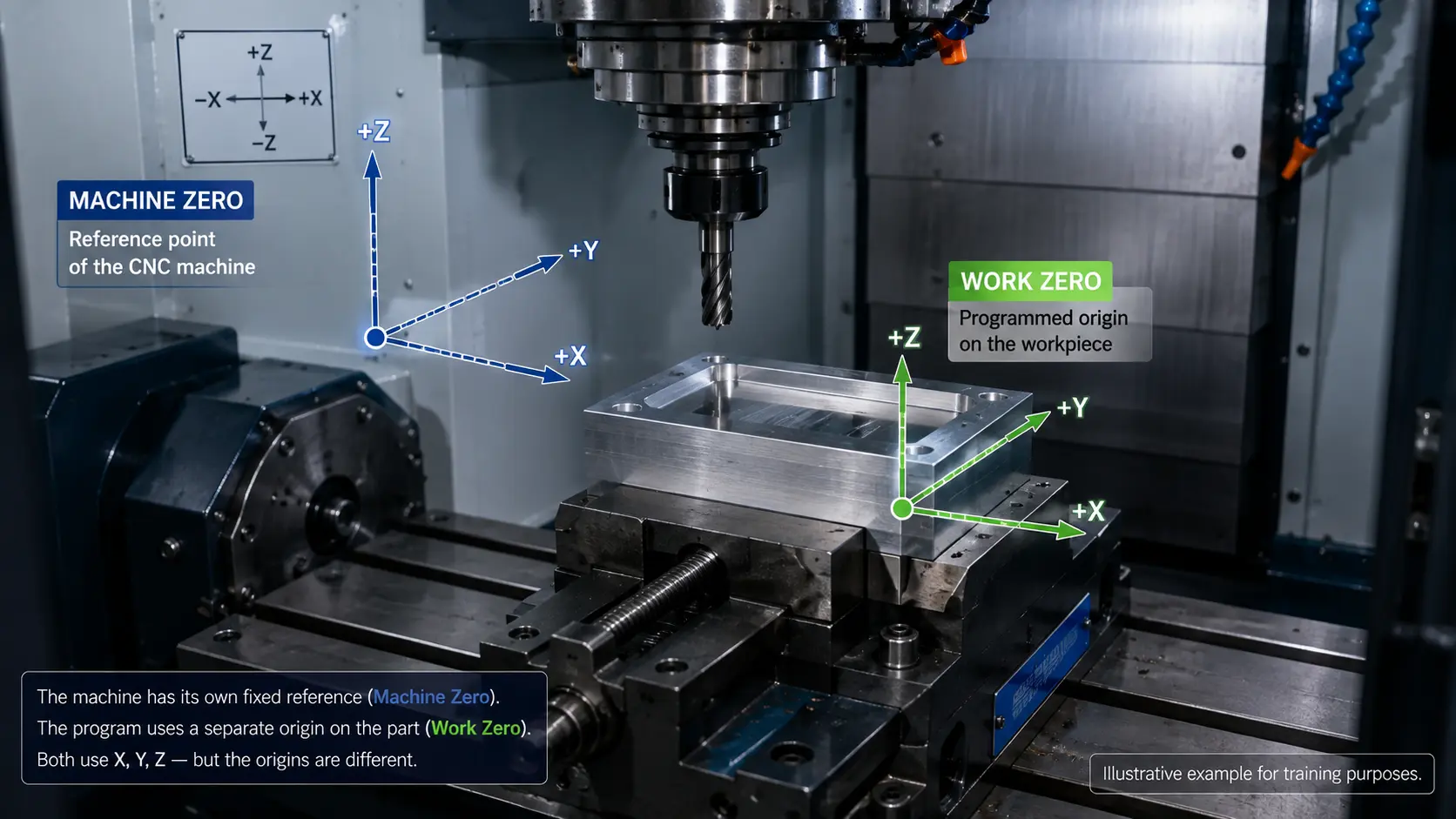
The machine coordinate system belongs to the machine itself. LinuxCNC describes the machine coordinate frame as the base reference from which other coordinate systems are derived. It becomes meaningful after the machine has established its reference through homing.
In a typical vertical machining environment, the axes may be understood broadly as X for horizontal movement along one table direction, Y for horizontal movement perpendicular to X, and Z for vertical tool/spindle direction. The exact positive directions and machine-zero location depend on the machine and controller.
“Machine zero is not a universal physical location shared by every CNC machine. The operator should always understand the particular machine being used.”
Homing establishes the machine reference
When a CNC machine starts, the control needs a reliable relationship between axis position and the physical machine. The homing or reference-return procedure establishes that relationship. After homing, the controller has a meaningful machine coordinate system. This operation should not be confused with locating the workpiece.
“Homing establishes where the machine is. Work offset setup establishes where the part is.”
Why not program everything from machine zero?
Imagine a component is clamped somewhere on a large CNC table. Suppose one corner lies at approximately X = -420, Y = -180 in machine coordinates. The drawing shows a hole located X = 20, Y = 15 from that corner.
If the programmer works directly in machine coordinates, the feature position must be translated manually into the machine frame. Every feature then depends on exactly where the workpiece happens to be clamped. Move the vise and the entire program effectively needs a new positional translation. That would be inconvenient.
Instead, CNC systems allow us to say: this point on the workpiece is X0 Y0. The program can then follow the component drawing naturally. That is the purpose of the work coordinate system.
What is work zero?
The terms work zero, program zero, part zero and workpiece origin are often used to describe the reference selected for programming the component.
Imagine a rectangular plate. We might select the lower-left corner of its top surface as X0, Y0, Z0. A feature located 20 mm to the right and 15 mm into the part can now be programmed simply as X20, Y15. The program is describing geometry relative to the component. The controller then needs to know where this X0 Y0 Z0 location is on the actual machine — that is what the work offset provides.
Work coordinate systems
Common work coordinate systems include G54, G55, G56, G57, G58 and G59. LinuxCNC additionally provides G59.1 through G59.3, while other controllers may provide their own extended work-offset ranges or implementations — do not assume every control offers exactly the same range.
The important concept is not the number of available offsets. It is what an offset means: a work offset establishes the relationship between the machine coordinate system and the workpiece coordinate origin.
What G54 actually means
Suppose the physical workpiece origin is located at some position within the machine coordinate system. The operator establishes that relationship and stores it in G54. Now the program says:
G54
G0 X0 Y0
The controller interprets X0 Y0 as the X/Y origin of the G54 work coordinate system. It does not interpret it as machine X0 Y0. This is probably the most important distinction for beginners.
G53 and G54 are not two versions of the same thing
G53 and G54 perform very different roles.
G53
G53 instructs the controller to use machine coordinates for that motion. LinuxCNC documents G53 as non-modal, meaning it applies to the relevant command rather than permanently switching the program into a machine-coordinate mode.
G53 G0 ...Conceptually, this line uses machine-coordinate positioning. The exact coordinate chosen must be appropriate for the particular machine. Do not assume, for example, that machine Z0 is universally the correct or safe retract position.
G54
G54 selects a work coordinate system. Unlike G53, the selected work coordinate system remains active until another coordinate system is selected.
| Code | Main reference |
|---|---|
| G53 | Machine coordinates |
| G54 | Work coordinate system 1 |
| G55 | Work coordinate system 2 |
| G56 | Work coordinate system 3 |
The codes become much easier to remember once their purpose is understood.
Why multiple work offsets are useful
Imagine three identical components clamped on the same machine table. Part 1 has its origin stored as G54, Part 2 as G55, and Part 3 as G56. Each component contains a hole at X20, Y15 relative to its own origin. The same programmed coordinates can therefore be used for all three.
LinuxCNC specifically notes that multiple work coordinate systems make it possible to repeat the same program at different workpiece locations without rewriting the geometry. This illustrates one of the most powerful ideas behind CNC coordinates: programmed geometry can be separated from physical fixture location.
The same coordinate can mean different physical positions
Suppose X20 Y15 is executed under G54. The tool moves to the point 20 units in X and 15 units in Y relative to the G54 origin. Now G55 is selected. The program again executes X20 Y15. The numerical coordinate is identical. The physical location may be completely different.
“Nothing about X20 Y15 changed. The reference changed. Coordinates should never be interpreted independently of the active coordinate system.”
Choosing a good program origin
There is no universal rule saying the origin must always be the top-left corner, bottom-left corner or centre. The most useful origin depends on the component and setup.
- Part corner — useful when drawing dimensions originate from two perpendicular edges.
- Part centre — useful for symmetrical geometry.
- Bore centre — useful when many features are dimensioned from a central bore or axis.
- Fixture datum — useful in repeated production where fixtures provide repeatable location.
A good coordinate origin should make the relationship between drawing, setup, program and inspection easy to understand.
Z zero deserves special attention
Errors in X and Y may place a feature in the wrong horizontal position. Errors in Z can also affect depth, clearance and contact with fixtures or workholding.
Suppose the program is written assuming Z0 represents the top surface of the workpiece. But the actual setup treats another surface as Z0. Then a command such as G1 Z-2.0 does not represent the physical cut the programmer expected. The number itself is not wrong. The reference assumption is wrong.
“Before running the program: what physical surface or datum does Z0 represent?”
Absolute and incremental positioning
Coordinate systems also interact with another CNC concept: absolute versus incremental positioning. These are normally selected with G90 for absolute and G91 for incremental. But G90/G91 should not be confused with G54/G55 — they answer different questions.
Work coordinate selection asks: which origin am I using? Absolute/incremental mode asks: how should the commanded movement be interpreted?
G90 — absolute positioning
Suppose G54 is active and we use G90 followed by G0 X50. Conceptually, the command says move to X50 relative to the active work coordinate origin. If the tool was previously at X20, the target is still X50.
G91 — incremental positioning
Now consider G91 followed by G0 X10. The command means move an additional 10 units from the current position in X. The reference logic is different.
| Codes | What they answer |
|---|---|
| G54 / G55 | Select the coordinate frame. |
| G90 / G91 | Control how motion values are interpreted. |
Beginners should learn these as separate concepts.
Work offsets are not tool offsets
Another frequent source of confusion is the word offset. A work offset and tool offset do not solve the same problem.
A work offset answers: where is the workpiece reference relative to the machine? A tool offset helps account for the geometry of the particular tool being used — for example, tool-length compensation becomes necessary because different cutters do not all extend from the spindle by exactly the same amount. That topic deserves its own detailed article.
“Work offsets locate the part. Tool offsets account for the tool.”
The coordinate stack
A useful mental model is: Machine → Workpiece → Feature → Tool.
- Machine — establish its physical reference.
- Workpiece — locate part zero through the work coordinate system.
- Feature — program geometry relative to part zero.
- Tool — account for the cutting tool correctly.
Many CNC positioning problems become easier when students identify which layer is actually wrong.
Local coordinate offsets
More advanced CNC programs can introduce additional local coordinate transformations. LinuxCNC documents G52, for example, as a local coordinate-system offset that can temporarily shift the active coordinate frame. This can be useful for repeated features — imagine four identical feature groups on one plate, where a local shift can allow the same relative geometry to be reused.
But for beginners, the learning sequence should remain machine coordinates, then work coordinates, then absolute/incremental positioning, before adding more advanced coordinate transformations.
Why G92 requires care
G92 can also modify coordinate relationships. However, its implementation and persistence require careful understanding of the particular control. LinuxCNC's documentation specifically discusses persistence of G92 offsets and the possibility that previous G92 values may affect later operation depending on settings and commands used.
“Do not use G92 casually because you have memorized what it "usually" does. Understand how your controller implements it.”
This broader warning applies throughout CNC programming. G-code concepts are standardized to a degree, but real controller behaviour can vary.
A simple worked milling example
Consider a rectangular plate, 100 mm × 60 mm, used here purely as an educational example. The programmer chooses the lower-left corner of the top surface as X0, Y0, Z0. Two hole centres are located at X25, Y20 and X75, Y20.
The program may contain conceptually:
G90
G54

G0 X25 Y20
...
G0 X75 Y20
Notice what the program does not contain. It does not need to say the plate is physically 312.4 mm from machine reference X. That relationship belongs to the work-offset setup. The program can remain written directly from part geometry.
Move the part without rewriting the geometry
Suppose the plate is moved to another position on the table. Its geometry has not changed. The hole locations remain X25, Y20 and X75, Y20 relative to part zero.
What changes is the relationship between machine coordinates and part zero. Update the appropriate work offset correctly and the same program geometry can remain valid. This is one reason coordinate systems are fundamental to flexible CNC production.
Correct-looking G-code can still produce the wrong toolpath
Consider G54 followed by G0 X25 Y20. Suppose the intended feature really is at X25 Y20 relative to the component datum. The program is correct. The CAM simulation is correct. But imagine G54 has been set 20 mm incorrectly in X. Now every coordinate in the toolpath is shifted. The toolpath geometry has not changed. The reference has.
“Correct G-code cannot compensate for an incorrect reference setup.”
Why simulation cannot verify everything
A software simulation may show a perfect toolpath. That proves something useful: the programmed motion appears correct relative to the coordinate assumptions inside the simulation. It does not automatically prove that the physical workpiece is located correctly, that the correct work offset has been selected, that the real Z datum matches the CAM datum, or that the actual fixture corresponds to the simulated setup.
Simulation verifies the virtual model. Physical setup still needs verification. This distinction is important for both CNC practice and engineering education.
Coordinate systems in CAM
Computer-aided manufacturing software does not remove the need to understand coordinates. During CAM setup, the programmer still defines stock orientation, machining origin, X direction, Y direction and Z direction. The post-processed G-code then assumes that the real machine setup corresponds to those choices.
A useful relationship is CAD geometry, then the CAM machining coordinate system, then G-code, then the machine work offset, then physical machining. If one link in this chain disagrees with the others, a correct CAM toolpath can still run at the wrong physical location.
Coordinate systems in programmatically generated G-code
The same principle applies when G-code is generated using Python or another software system. Software can calculate G0 X40 Y30 accurately. But the generated coordinate still depends on assumptions such as the active coordinate system, units, axis orientation, absolute/incremental mode and work zero.
This is something I have found particularly useful when working with CNC and generated G-code. Once machine zero, work zero and programmed coordinates are clearly separated, the program becomes easier to reason about.
Toolpath verification also becomes more meaningful because the question changes from "are these X and Y numbers correct?" to "are these coordinates correct relative to the reference system that will actually be used?" That is a much stronger verification question.
Coordinate verification before machining
CNC verification should be performed according to the specific machine, controller and workplace procedure. But conceptually, several questions should be answered before the machining cycle is trusted.
| Question | Why it matters |
|---|---|
| Which work coordinate system is active? | Does the program expect G54, G55 or another offset? |
| What physical location represents X0 Y0? | Does it match the programmed datum? |
| What represents Z0? | Top of stock, a fixture datum, or another reference? |
| Do tool assumptions match the setup? | The work reference can be correct while tool data are wrong. |
| Does the programmed coordinate range make sense? | Are motions consistent with machine travel, fixture position and workpiece dimensions? |
| Has the setup been verified appropriately? | Graphical checking, program review, single-block operation or another approved method. |
The exact safe procedure should always follow the specific machine/controller and workplace requirements rather than a generic internet recipe.
Common CNC coordinate-system mistakes
- Confusing machine zero with work zero. They serve different purposes.
- Selecting the wrong work offset. A correct program under G54 may be physically wrong if G55 is active.
- Incorrect Z reference. This can affect depth and clearance seriously.
- Forgetting G90 or G91 state. Absolute and incremental interpretation can produce very different motion.
- Assuming CAM zero automatically equals physical work zero. The physical setup still needs to match the CAM assumption.
- Changing an offset without verification. Changing one reference value can shift the complete toolpath.
- Confusing tool offsets with work offsets. One locates the workpiece; the other relates to tool geometry.
- Assuming every controller behaves identically. Specific G-code implementation should be verified against controller documentation.
- Ignoring modal state. The controller may retain settings from earlier commands.
- Assuming simulation proves the physical setup. Simulation cannot know that a real work offset was entered incorrectly unless the virtual setup includes that error.
What engineering students should remember
If the details become confusing, return to five questions.
- Where is machine zero? That establishes the machine reference.
- Where is part zero? That defines the programming reference.
- Which work offset connects them? For example, G54.
- What does the programmed coordinate mean relative to part zero? For example, X25, Y20.
- Where will the physical tool actually move? That is the result of all the coordinate relationships acting together.
This sequence is more useful than memorizing G-codes independently.
Key takeaway
CNC coordinate systems exist because the machine and the component do not need to share the same zero. The machine maintains its own coordinate reference. The workpiece is located somewhere inside that machine space. A work offset connects the two. The program can then describe component geometry relative to a convenient part origin.
This gives us the central relationship: machine coordinate system, work offset, program coordinate, resulting in physical machine position. Once this relationship is understood, concepts such as G53, G54, G55, G90 and G91 become much easier to interpret.
“Never ask only, "What is the coordinate?" Ask, "What is the coordinate relative to?"”
That question prevents many of the conceptual errors that make CNC programming seem more difficult than it really is.
References and further reading
- LinuxCNC — Coordinate Systems. Current technical reference for machine coordinates, work coordinate systems, G53, G54–G59.3, G52 and G92 behavior.
- LinuxCNC — G-Code Overview. Useful companion reference for modal groups and general interpretation of CNC G-code.