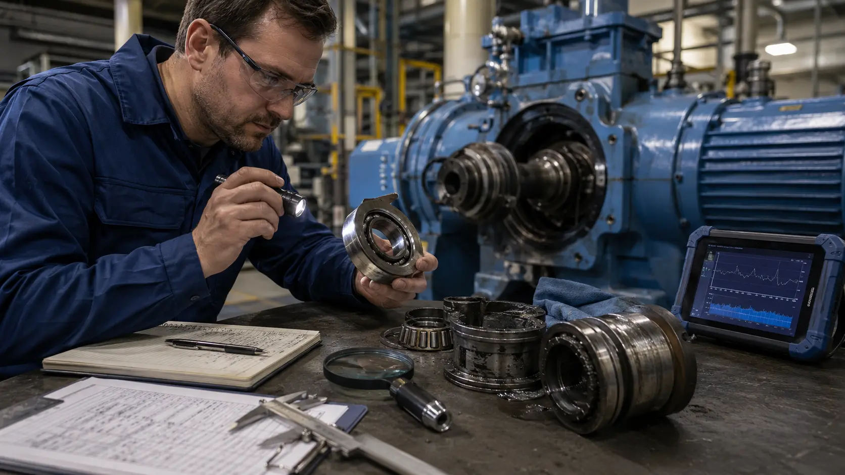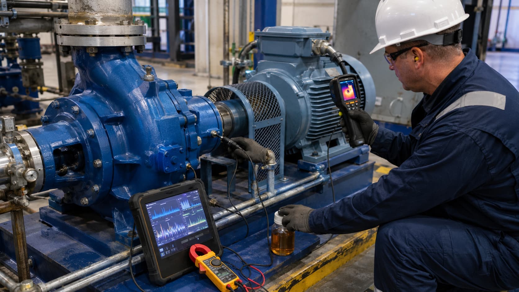
The physical deterioration always happens first.
A bearing does not begin failing because a vibration sensor says it is failing.
A surface defect develops. Lubrication deteriorates. A shaft becomes misaligned. A rotor becomes unbalanced. A gear tooth wears.
The machine then responds physically.
It may:
- Vibrate differently
- Generate more heat
- Release wear debris into the lubricant
- Require different motor torque or electrical current
Condition monitoring works by observing those changes before they become unacceptable failures.
That sounds straightforward, but an important engineering question follows:
“Which physical change should we measure?”
Vibration is powerful, but it does not reveal every failure mode.
Temperature is easy to measure, but it can be nonspecific.
Oil can tell us what is happening inside a lubricated system, but only when sampling and interpretation are reliable.
Motor-current analysis can provide useful information without mounting a mechanical sensor directly on the rotating assembly, but load and control conditions can influence the signal.
There is therefore no single universal "best" condition-monitoring technique.
ISO 17359:2018 provides general guidance for establishing machinery condition-monitoring programmes rather than prescribing one sensor for every machine. It remains current after ISO's 2023 review.
The more useful principle is:
“Start with the failure mechanism. Then choose the measurement that provides meaningful evidence of the physical change that mechanism creates.”
Condition monitoring starts with failure physics
Consider a rolling-element bearing.
Possible deterioration may involve:
- Lubrication problems
- Surface damage
- Contamination
- Excessive load
- Alignment problems
Different stages or mechanisms can produce different observable effects.
A developing localized surface defect may produce repeated impacts as rolling elements pass over it.
Those impacts can generate vibration.
Poor lubrication may increase friction.
That can influence:
- Temperature
- Vibration
- Lubricant condition
Wear may release particles into the lubricant.
The monitoring method should therefore follow a chain:
Failure mechanism → physical effect → measurement → interpretation
This is more reliable than beginning with:
“We own a vibration sensor. What can we diagnose with it?”
Detection, diagnosis and prognosis are different
These terms are sometimes used as though they mean the same thing.
They do not.
Detection
Has machine behaviour changed enough to suggest an abnormal condition?
Diagnosis
What fault or physical mechanism most likely explains the observed change?
Prognosis
How might the condition develop in future?
That distinction matters because a condition-monitoring signal may be excellent at detecting change without being sufficient to identify its cause.
ISO 13379-1:2025 now provides the current general guidance for machinery condition-monitoring data interpretation and diagnostic approaches. It explicitly addresses how appropriate diagnostic approaches should be selected for particular machine-system applications.
A maintenance system therefore often progresses through:
Monitor → detect → diagnose → assess severity → decide maintenance action
Predictive maintenance may later add prognosis to this chain.
Establish normal behaviour first
It is difficult to identify deterioration if normal machine behaviour is poorly understood.
A rotating machine's measurements can depend on:
- Rotational speed
- Load
- Process condition
- Machine configuration
- Ambient temperature
- Operating mode
Suppose vibration is measured today and then again next month.
The second reading is higher.
Has the machine deteriorated?
Perhaps.
But perhaps:
- Speed increased
- Process load changed
- The measurement location changed
- A different operating state was measured
A meaningful baseline should therefore describe both the measurement and its operating context.
Condition monitoring becomes far more useful when it asks:
“Is the machine changing under comparable conditions?”
rather than simply:
“Is today's number larger than last month's?”
Vibration analysis: one of the strongest rotating-machinery tools
Rotating machines naturally generate vibration.
Some vibration is normal.
The engineering task is to determine whether its magnitude, frequency content, waveform or trend has changed in a meaningful way.
ISO 13373-1 provides general vibration-condition-monitoring guidance covering measurement parameters, transducers, mounting locations, machine operating conditions, data collection, signal conditioning, and both continuous and periodic monitoring. The standard was reconfirmed in 2024 and remains current.
Overall vibration
A single overall vibration value can be useful for:
- General condition trending
- Detecting significant deterioration
- Screening multiple assets
Its limitation is that it compresses complex vibration behaviour into one value.
The machine can therefore change internally while the overall value tells us little about the physical cause.
Time waveform
A time waveform shows vibration amplitude changing with time.
It can reveal features such as:
- Impacts
- Modulation
- Irregular behaviour
- Periodic events
Waveforms are useful because some machine behaviour is easier to recognize in time than in frequency.
Frequency spectrum
Frequency analysis separates vibration into frequency components.
Instead of only asking:
“How much is the machine vibrating?”
we can ask:
“At which frequencies is the vibration occurring?”
That matters because machine components create mechanical events at characteristic rates related to:
- Shaft rotation
- Gears
- Rolling elements
- Process forces
For example, imbalance often produces a strong component associated with rotational speed.
Misalignment may generate additional harmonic behaviour.
Rolling-element bearing defects can produce repeated impacts and higher-frequency responses.
Gear problems may influence gear-mesh-related frequencies and sideband behaviour.
But these are not automatic diagnoses.
A spectral feature is evidence—not proof of a fault by itself.
Interpretation still depends on:
- Machine configuration
- Shaft speed
- Gear geometry
- Bearing geometry
- Load
- Sensor position
- Measurement history
Vibration sensors also need good measurement practice
An expensive vibration analyser cannot correct poor measurement setup.
Important choices include:
- Sensor type
- Measurement direction
- Mounting method
- Location
- Sampling
- Frequency range
A sensor placed far from the mechanical path of interest may receive a weak or distorted version of the signal.
Loose mounting can introduce measurement problems.
Measurements taken at inconsistent locations reduce trend quality.
That is why condition monitoring requires disciplined data collection rather than occasional numbers.
ISO 13373-1 specifically emphasizes transducer selection, location, attachment and operating conditions as part of reliable vibration monitoring.
Temperature monitoring: simple but valuable
Temperature is one of the easiest machine-health quantities to understand.
Heat can increase because of:
- Friction
- Inadequate lubrication
- Overload
- Poor cooling
- Bearing problems
- Electrical losses
- Process changes
Temperature monitoring can therefore provide an excellent early indication that something in the machine's energy balance has changed.
It also has useful practical advantages.
Sensors can often be inexpensive, permanently installed and easy to trend.
But temperature also has a major limitation:
“It is often nonspecific.”
An increasing bearing temperature tells us something changed.
It does not necessarily tell us what changed.
The cause could involve:
- Lubrication
- Load
- Ambient conditions
- Speed
- Cooling
- Mechanical condition
Temperature becomes considerably stronger when interpreted alongside operating context and another complementary measurement.
Absolute temperature and temperature trend are different things
Suppose a bearing normally stabilizes within a particular temperature range under a known duty.
A slow rise across otherwise comparable operating conditions can be more informative than one isolated high reading.
Similarly, two machines may operate at different normal temperatures because of differences in configuration, loading, installation or environment.
This makes baselines important again.
A generic temperature threshold may be useful where manufacturers or engineering limits define one.
But condition monitoring often gains greater sensitivity from:
“Change relative to normal behaviour.”
Oil analysis looks inside the lubricated system
Vibration observes machine dynamics.
Temperature observes thermal response.
Oil analysis offers another perspective: what is happening to the lubricant and what evidence of internal wear is entering it?
This makes it especially useful for machines such as:
- Gearboxes
- Turbines
- Compressors
- Large bearing systems
- Hydraulic systems
Oil analysis can address two broad questions.
What condition is the lubricant in?
Possible areas include:
- Viscosity
- Contamination
- Water
- Oxidation or degradation
- Additive condition where relevant
This helps answer whether the lubricant remains capable of performing its function.
What does the lubricant tell us about the machine?
Wear processes can release material into the lubricant.
Analysis of particle quantity, particle size, morphology and elemental composition can provide evidence about internal wear.
The lubricant therefore becomes an information carrier from places that may be physically difficult to inspect.
Sampling quality can determine whether oil analysis is useful
The laboratory can perform an extremely precise analysis.
But if the sample is unrepresentative, the precision does not solve the problem.
Sampling can be affected by:
- Where the sample is taken
- Whether the machine was operating
- Contamination during sampling
- Stagnant oil
- Inconsistent procedures
- Sample-container cleanliness
A useful reliability principle is:
“A poor sample can produce a very precise laboratory result about the wrong oil condition.”
Trend consistency therefore matters just as much in oil analysis as it does in vibration.
Motor-current analysis: observing mechanics electrically
An electric motor responds to the mechanical load connected to it.
Changes in the rotating system can therefore influence electrical behaviour.
Motor-current analysis can provide information relevant to:
- Motor electrical faults
- Rotor behaviour
- Load changes
- Some mechanically induced torque variations
One advantage is that the measurement can sometimes be obtained electrically without mounting an additional sensor directly on the rotating mechanical component.
This can be attractive where access is difficult, the equipment already exposes electrical measurements, or non-invasive monitoring is valuable.
But current is not automatically a mechanical diagnosis.
Motor current can also change because of:
- Production load
- Control commands
- Supply conditions
- Speed
- Operating state
The engineering challenge is therefore similar to the other techniques:
“Separate normal operational variation from condition-related change.”
Motor-current and vibration measurements answer different questions
It is tempting to see motor-current monitoring as a cheaper replacement for vibration sensors.
That is not the best framing.
They observe the machine from different physical perspectives.
Vibration measures mechanical dynamic response more directly.
Motor-current analysis observes electrical behaviour that may contain information about the motor and mechanical load.
Depending on the failure mechanism, one may be more sensitive, more direct or easier to install and interpret.
They can also be complementary.
Operating context can completely change interpretation
Imagine a pump.
Motor current increases.
At the same time vibration also changes slightly.
Possible conclusion:
“Machine fault.”
But what if process demand increased?
The pump may simply be operating at a different point.
Now consider a machine tool.
Vibration rises during cutting.
Without knowing spindle speed, feed, tool engagement, material and machine state, the increase could easily be misinterpreted.
This is one of the most important principles in modern condition monitoring:
“Condition data without operating context can make normal machine behaviour look abnormal.”
This becomes even more important when data are later used for machine learning.
An algorithm can learn operating-state differences just as easily as it can learn degradation.
Trends are often more useful than isolated readings
A single measurement answers:
“What did I observe at this moment?”
A trend answers:
“How is the condition evolving?”
Imagine several weeks of comparable operation.
The following trends may become meaningful:
- Increasing vibration
- Slowly rising bearing temperature
- Increasing wear particles
- Changing motor-current pattern
Each measurement alone might still lie within a broadly acceptable range.
The direction of change may nevertheless justify further investigation.
This is one reason predictive maintenance begins with good condition-monitoring history.
Prediction requires evidence of how condition evolves.
Four techniques, four different windows into the machine
The methods can be summarized conceptually.
Vibration
Best suited to observing:
- Machine dynamics
- Imbalance
- Misalignment
- Looseness
- Bearing and gear-related behaviour
Temperature
Useful for observing:
- Frictional heating
- Cooling performance
- Overload
- Lubrication-related heat
- General thermal abnormality
Oil
Useful for observing:
- Lubricant condition
- Contamination
- Wear debris
- Internal wear processes
Motor current
Useful for observing:
- Motor electrical behaviour
- Load
- Some electromechanical abnormalities
None provides a complete picture.
ISO 13373-1 makes this same broader point: vibration monitoring is only one component of machine condition monitoring, which can also involve oil analysis, thermography, temperatures, pressures and process variations.
Combining methods can strengthen diagnosis
Suppose a gearbox shows increasing vibration plus increasing wear debris.
The two signals arise through different physical mechanisms.
Together they may provide stronger evidence of internal deterioration than either alone.
Similarly, bearing vibration increase plus bearing temperature increase can support a stronger investigation.
This concept is sometimes called data or sensor fusion when implemented formally.
But the underlying engineering principle is simpler:
“Independent physical evidence can strengthen a diagnosis.”
That does not mean every asset needs four monitoring technologies.
More sensors are not automatically better
Every measurement introduces cost.
That may include:
- Sensor hardware
- Installation
- Wiring or communication
- Acquisition
- Storage
- Calibration
- Maintenance
- Analysis
- Specialist time
If an additional sensor does not change the maintenance decision, its value may be limited.
A 2025 systematic review involving NIST researchers emphasizes that condition-monitoring technologies should be evaluated not only technically but also in terms of engineering and economic value.
This leads directly to asset criticality.
Continuous or periodic monitoring?
Not every machine needs continuous online monitoring.
Continuous monitoring becomes attractive when:
- Failure develops quickly
- Asset criticality is high
- Downtime is expensive
- Equipment is inaccessible
- Automatic alarms are valuable
- Machine behaviour changes rapidly
Periodic monitoring may be sufficient when:
- Degradation develops slowly
- Assets are easily accessible
- Failure consequences are moderate
- Route-based monitoring is economical
ISO 13373-1 explicitly covers both continuous and non-continuous vibration-monitoring approaches.
Monitoring frequency should therefore follow:
“Failure-development time plus asset consequence.”
not simply:
“How frequently the sensor can collect data.”
Condition monitoring and predictive maintenance are related but different
Condition monitoring tells us about the observed health of the asset.
Predictive maintenance goes further by using condition information to support decisions about future maintenance needs.
A simple progression is:
Measure → detect change → diagnose → assess degradation → predict → maintenance decision
This is why good predictive-maintenance systems begin with good condition-monitoring engineering.
An advanced machine-learning algorithm cannot compensate for an inappropriate measurement, poor sensor installation, missing operating context or inconsistent data.
The data pipeline begins in the physical machine.
How I think about condition-monitoring signals
My own engineering, workshop, maintenance and research exposure has made one point particularly useful: machine-health measurements should not be treated as abstract numbers separate from the equipment.
The signal should always lead back to a physical question.
Why should vibration change? What could create additional heat? What could produce wear particles? Why should motor load change?
The monitoring technology is most useful when it improves that mechanical reasoning rather than replacing it.
That perspective is also important when moving from conventional condition monitoring into AI-based predictive maintenance.
Before asking:
“Which algorithm should I train?”
the stronger question is:
“Which physical signal should contain evidence of the degradation I want to detect?”
The Condition Monitoring Selection Logic
A practical monitoring programme can be designed through eight steps.
1. Identify critical failure modes
Begin with the asset.
What failures matter?
Examples may include:
- Bearing damage
- Imbalance
- Gear wear
- Lubrication failure
- Motor faults
Do not begin with the sensor catalogue.
2. Identify the physical symptom
Ask what each failure should physically produce.
Could it create vibration, heat, particles or torque/load variation?
This establishes the measurement opportunity.
3. Select the measurement
Choose the technique most directly related to the physical symptom.
That might be vibration, temperature, oil, current, or a combination.
4. Define operating context
Record relevant conditions such as speed, load, process state and environmental condition.
Without context, comparison becomes weaker.
5. Establish baseline behaviour
Determine what normal looks like.
Ideally across representative operating conditions.
6. Trend and compare
Look for meaningful change.
Do not rely only on isolated measurements.
7. Confirm ambiguous findings
Where consequences justify it, seek complementary evidence.
For example, a vibration change plus temperature or oil evidence.
8. Define the maintenance action
A condition-monitoring programme is incomplete if nobody knows what happens after an alarm.
Define:
- Inspection trigger
- Diagnostic step
- Maintenance threshold
- Escalation process
The final objective is not data collection.
It is a better maintenance decision.
Common condition-monitoring mistakes
Several recurring mistakes can reduce the value of even sophisticated systems.
Monitoring whatever is easiest to measure
Sensor availability should not determine failure strategy.
Ignoring operating conditions
Load and speed can dominate machine signals.
Moving measurement locations
Trend data become harder to compare.
Treating one spectral peak as a diagnosis
Frequency patterns require physical interpretation.
Taking inconsistent oil samples
Sampling quality can undermine laboratory analysis.
Using generic alarm limits without machine context
Thresholds should reflect applicable standards, OEM guidance, baseline behaviour and engineering judgement.
Collecting data without defining action
A dashboard full of measurements does not create reliability by itself.
Key takeaway
Condition monitoring should not start with:
“Which sensor should we install?”
Start with:
“How can this machine fail, and what physical evidence would that failure create?”
If the failure primarily changes dynamics, vibration may be strongest.
If it increases friction or heat, temperature may provide useful evidence.
If deterioration affects a lubricated interface, oil may reveal lubricant condition or wear debris.
If the motor electrically reflects changing load or motor condition, current analysis may add another useful perspective.
The techniques become strongest when they are selected according to failure physics, operating context, asset criticality and the maintenance decision they need to support.
The goal is not to collect the most machine data.
It is to collect the right evidence early enough to make a better engineering decision.
References and further reading
- ISO 17359:2018 — Condition monitoring and diagnostics of machines — General guidelines. The current general framework for establishing machine condition-monitoring programmes.
- ISO 13373-1:2002 — Condition monitoring and diagnostics of machines — Vibration condition monitoring — Part 1: General procedures. Covers machinery vibration measurement, transducers, locations, attachment, operating conditions, continuous and periodic monitoring. It was reconfirmed in 2024 and remains current.
- ISO 13379-1:2025 — Condition monitoring and diagnostics of machine systems — Data interpretation and diagnostics techniques — Part 1: General guidelines. Current guidance on condition-monitoring interpretation and diagnostic approaches.
- Dadfarnia, Sharp & Herrmann — Comprehensive evaluations of condition monitoring-based technologies in industrial maintenance: A systematic review. Journal of Manufacturing Systems, 2025. Useful review of technical and economic evaluation of condition-monitoring technologies in industrial maintenance.