A machine-learning model can report 95%, 98% or even 99% accuracy and still be a poor predictive-maintenance system.
That sounds contradictory until we separate two questions.
The first is:
“How well does the model perform on the dataset used to evaluate it?”
The second is:
“Does the result provide trustworthy information about a real CNC machine condition that maintenance can act on?”
Those questions are related, but they are not equivalent.
Predictive maintenance sits at the intersection of mechanical condition, sensors, data, statistical learning and maintenance decision-making. If any link in that chain is weak, increasing model complexity may produce a more sophisticated algorithm without producing better engineering information.
This is one of the most important lessons I am encountering in my own work on CNC predictive maintenance. I have worked with condition data and experimented with machine-learning algorithms and features, but the deeper research question is not simply which model produces the highest score.
The harder question is:
“What evidence would make that prediction trustworthy enough to inform maintenance?”
Start with the machine failure, not machine learning
It is tempting to begin a predictive-maintenance project by selecting an algorithm.
- Random Forest?
- Support Vector Machine?
- Neural network?
- LSTM?
- Transformer?
That sequence starts too late.
The first question should be:
“What physical failure or degradation process are we trying to understand?”
A CNC machine contains many potential failure locations:
- Spindle bearings
- Ball screws
- Guideways
- Motors and drives
- Lubrication systems
- Tooling
- Coolant systems
- Hydraulics or pneumatics
- Controller hardware
These failure mechanisms do not produce identical signals. A bearing problem may alter vibration characteristics. A lubrication problem may produce changes in friction, temperature or vibration. Tool wear may influence cutting forces, vibration, acoustic behaviour and workpiece quality. A servo-axis problem may appear differently again.
NIST research on machine-tool diagnostics has demonstrated why physical failure understanding matters. Work on spindle diagnostics found that simple vibration metrics can be insufficient because measured behaviour can contain both defect-related motion and the machine's structural dynamics.
The model therefore cannot rescue a poorly defined engineering problem.
Before asking:
“Which model should detect this?”
ask:
“What exactly is changing physically, and how could we observe it?”
Detection, diagnosis and prognosis are not the same task
“AI predictive maintenance” is often used as though it describes one problem. It does not.
Three related tasks should be distinguished.
Anomaly detection
The question is:
“Does current machine behaviour differ significantly from what is considered normal?”
Anomaly detection can be useful where detailed fault labels are limited. It may identify that something has changed without confidently stating what failed.
Diagnosis or fault classification
Here the question becomes:
“Which known condition or fault is present?”
For example:
- Normal
- Bearing-related abnormality
- Tool wear
- Misalignment
This requires meaningful condition categories and evidence that the categories represent real physical states.
Prognosis
Prognosis asks something harder:
“How is the condition likely to evolve?”
or:
“How much useful operating life may remain?”
NIST's prognostics and health-management research treats monitoring, diagnostics and prognostics as connected but distinct capabilities that support maintenance action.
A model that distinguishes healthy and faulty observations extremely well is therefore not automatically capable of predicting remaining useful life. The claim made by the model must match the experiment used to validate it.
Measure something that actually reflects degradation
A predictive-maintenance system ultimately depends on measurements.
Possible CNC condition signals include:
- Vibration
- Temperature
- Electrical current
- Acoustic information
- Force
- Speed
- Load
- Controller variables
- Lubricant-related information
ISO 17359 provides general guidance for establishing machinery condition-monitoring programmes and explicitly treats condition monitoring as a structured process rather than merely a sensor installation exercise.
The engineering problem is determining whether the selected measurement actually carries useful information about the targeted condition.
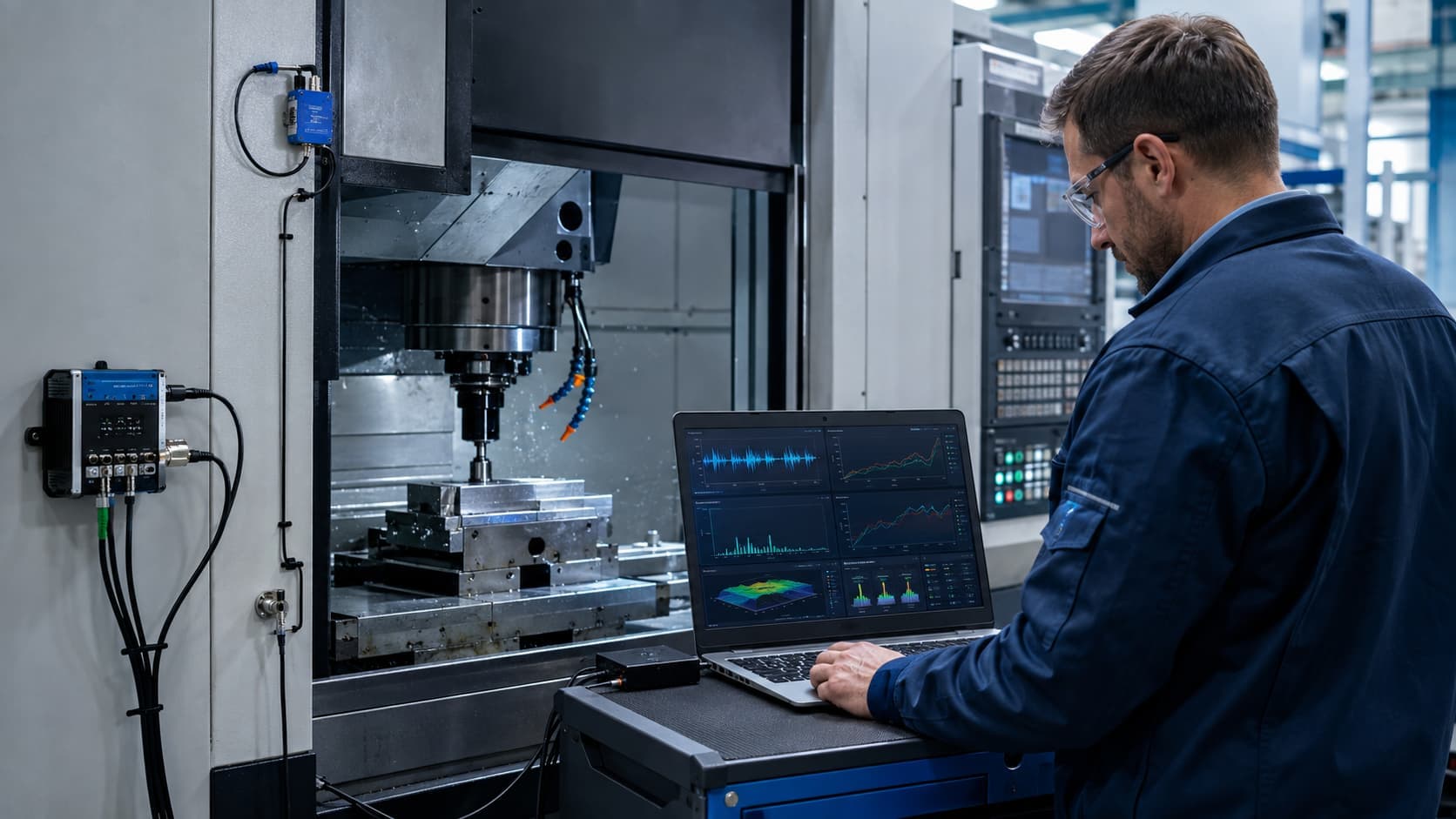
Consider spindle vibration. An accelerometer may detect considerable vibration. But vibration is influenced by more than bearing health.
The measured signal can contain effects from:
- Spindle rotation
- Cutting
- Tool engagement
- Structural resonances
- Machine dynamics
- Workpiece conditions
- Other mechanical sources
The correct question is not:
“Is there vibration?”
It is:
“Does the measured vibration contain a repeatable and interpretable signature of the degradation we care about?”
That distinction is fundamental.
More data is not the same as better data
Modern industrial systems can generate enormous datasets. That does not guarantee that the data are suitable for predictive maintenance.
Useful condition data require attention to:
- Sensor placement
- Sampling rate
- Synchronization
- Calibration
- Noise
- Missing values
- Machine operating state
- Units
- Timestamps
- Maintenance interventions
NIST manufacturing research has shown that combining machine-controller information with external sensor information can improve the representation of machine condition.
This is particularly valuable for CNC equipment because external condition measurements rarely exist in isolation.
Imagine that vibration increases. Without additional context, several explanations may be plausible:
- Degradation developed
- Spindle speed changed
- Feed changed
- Cutting depth changed
- Tooling changed
- Material changed
- Machining operation changed
That leads to an important rule:
“Condition signals need operating context.”
The hardest data problem may be ground truth
Collecting sensor readings is often easier than obtaining trustworthy labels.
A machine can produce millions of vibration measurements. But how many of those observations have reliable labels such as:
- Confirmed healthy
- Early-stage degradation
- Known bearing defect
- Confirmed tool wear
- Confirmed lubrication problem?
Machines normally spend far more time operating without catastrophic failure than failing. That means predictive-maintenance datasets can contain many normal observations and relatively few genuine failure examples.
The rare examples may also be difficult to label.
- Was the abnormal vibration really caused by a damaged bearing?
- Was the component inspected?
- Was it replaced?
- Did maintenance confirm the failure?
Without reliable ground truth, the model may learn distinctions that do not correspond to the physical condition we think we are modelling.
This creates one of the most important practical principles in predictive-maintenance research:
“Large datasets do not compensate for weak labels.”
Operating conditions can look like faults
CNC equipment rarely operates at one fixed condition. Consider a spindle. Its measured behaviour may change with:
- Rotational speed
- Cutting load
- Tool
- Material
- Depth of cut
- Feed
- Machining operation
Suppose a model is trained primarily using low-load operation as “healthy” and higher-load observations as “faulty.” The model might achieve excellent classification performance.
But it may have learned low load versus high load rather than healthy versus degraded. That is a serious experimental-design problem.
Condition monitoring becomes stronger when operational variables are included in the interpretation. For example, vibration + spindle speed + load + operating state may provide a more meaningful description than vibration alone.
This connects directly with IIoT machine integration, because controller information can provide context for externally measured condition signals.
Features should carry physical meaning where possible
Raw sensor signals are often transformed before being used by conventional machine-learning models.
For vibration data, possible representations discussed in condition-monitoring research can include statistical, time-domain and frequency-domain characteristics.
The important question is not whether a feature sounds sophisticated. It is:
“Why should this feature change when the targeted mechanical condition changes?”
Feature engineering is strongest when the mathematical representation remains connected to the underlying machine behaviour.
Deep-learning systems may learn representations automatically, but the same engineering responsibility remains. A model still has to demonstrate that the learned information generalizes beyond the training observations.
Complexity does not remove the need for physical reasoning.
Avoid training and testing on the same operating episode
One of the easiest ways to obtain overly optimistic model performance is to split time-dependent machine data incorrectly.
Imagine collecting thousands of consecutive vibration windows from one CNC operating run. Then randomly divide them:
- 80% training
- 20% testing
Neighbouring windows may be extremely similar. The model may effectively see almost the same physical operating event during training and testing.
The reported accuracy can then answer:
“Can the model recognize observations similar to ones it already saw?”
rather than the more important question:
“Can the model recognize the condition in genuinely unseen operation?”
Stronger evaluation may therefore separate data by:
- Operating run
- Time period
- Fault episode
- Machine
- Experiment
The exact method depends on the research question. But the principle remains:
“The test dataset should represent the kind of unfamiliar condition the deployed model will actually encounter.”
Otherwise, data leakage can disguise memorization as generalization.
Why accuracy can be misleading
Suppose a dataset contains:
- 9,800 healthy observations
- 200 fault observations
That means 98% of the data are healthy.
Now imagine a model that predicts healthy for every single observation.
Its overall accuracy is 98%.
Yet it detects none of the faults. For maintenance purposes, it is nearly useless.
That is why predictive-maintenance evaluation should consider what different errors mean.
False positive
The system indicates a fault when the machine is actually healthy.
Possible consequences:
- Unnecessary inspection
- Unnecessary downtime
- Wasted maintenance labour
- Declining confidence in the monitoring system
False negative
The system reports healthy operation while degradation is actually present.
Possible consequences:
- Missed intervention
- Unplanned failure
- Secondary damage
- Production loss
- Potentially safety or quality consequences
Those errors do not necessarily have equal cost.
Metrics such as precision, recall, specificity, confusion matrices or related measures can therefore be more informative than accuracy alone.
But even those numbers require engineering interpretation.
The important question is:
“Which errors can the maintenance process tolerate?”
Start with a baseline before reaching for deep learning
AI research frequently encourages movement toward increasingly complex models. That is not automatically good engineering.
Before deploying a complex neural architecture, compare it with simpler approaches.
Depending on the problem, useful baselines might include:
- Engineering thresholds
- Statistical rules
- Simple classifiers
- Conventional machine-learning models
A baseline provides something essential: evidence that the added complexity actually improves the engineering outcome.
A complex model may require:
- More training data
- Additional computation
- More difficult validation
- Harder debugging
- More difficult deployment
- Reduced interpretability
If a simpler method identifies the important condition reliably enough, complexity may provide little practical benefit.
The goal is not to use the most advanced algorithm. The goal is to make the best supported decision.
Example: spindle-bearing condition monitoring
Consider a hypothetical CNC spindle-monitoring project.
The objective is:
“identify developing abnormal spindle-bearing behaviour early enough to justify inspection.”
That statement is already more precise than:
“Predict CNC machine failure.”
Step 1 — Define the condition
- What counts as normal?
- What evidence defines abnormal bearing behaviour?
- How will the condition eventually be confirmed?
Step 2 — Select measurements
Possible information might include:
- Vibration
- Temperature
- Spindle speed
- Spindle load
Research on machine-tool diagnostics shows that vibration and temperature can be relevant in machine-tool degradation studies, while NIST work has also examined robust feature design for ball-screw degradation using these kinds of signals.
Step 3 — Collect operating context
Record the machine state associated with each condition measurement. Without this, normal changes in operation may be mistaken for degradation.
Step 4 — Establish ground truth
Maintenance inspection, controlled experiment or known component condition must establish what the labels represent.
Step 5 — Prepare the data
Possible work includes:
- Synchronization
- Filtering
- Segmentation
- Normalization
- Missing-data handling
Step 6 — Represent the condition
Features may be engineered manually or learned by the model. The choice should match the signal and research question.
Step 7 — Establish a baseline
Determine how a simple condition threshold or conventional method performs.
Step 8 — Train the model
Now model choice becomes meaningful.
Step 9 — Validate on genuinely unseen operation
Hold out complete runs or other independent condition data where appropriate.
Step 10 — Interpret the errors
- How often are faults missed?
- How often are healthy states incorrectly flagged?
Step 11 — Define the maintenance action
Does the prediction:
- Trigger inspection?
- Increase monitoring frequency?
- Schedule maintenance?
- Require another diagnostic test?
Only here does the machine-learning output become part of predictive maintenance.
Prediction should include uncertainty
Engineering predictions should not appear more certain than the evidence supports.
A model may output Bearing fault detected, but several additional questions matter:
- How confident is the prediction?
- Is the machine operating within conditions represented in training?
- Is sensor quality acceptable?
- Is this observation unlike anything the model has previously seen?
A trustworthy system should make uncertainty visible where possible.
The aim is not to make every maintenance engineer understand the mathematics of probability calibration. It is to avoid presenting a statistical inference as unquestionable mechanical truth.
A model that works today may not work forever
Deployment is not the end of validation. The machine changes. The environment changes.
Possible changes include:
- Component replacement
- Tool changes
- Sensor ageing
- Sensor repositioning
- Production changes
- Different materials
- Different operating regimes
- Machine wear
The statistical distribution seen by the model can therefore shift.
A system needs continuing monitoring not only of the machine but also of the model and data pipeline.
Questions include:
- Are sensor distributions changing?
- Is model confidence changing?
- Are false alarms becoming more common?
- Is new labelled maintenance information available?
- Should the model be recalibrated or retrained?
Predictive-maintenance AI itself requires maintenance.
Can one CNC model simply be transferred to another machine?
Usually this should not be assumed.
Two machines of the same general type may differ in:
- Structural dynamics
- Sensors
- Spindle design
- Installation
- Tooling
- Control systems
- Process conditions
- Wear history
A model may unintentionally learn machine-specific characteristics. Before transferring it, performance should be independently evaluated on the new equipment.
Generalization across machines is therefore a research question—not an automatic property of machine learning.
Where digital twins may eventually fit
Digital twins can extend predictive-maintenance architectures by combining physical machine data with computational representations of machine behaviour.
NIST has demonstrated CNC digital-twin research with potential monitoring and predictive-maintenance applications when combined with machine learning.
But a digital twin does not remove the fundamental requirements discussed here. It still needs:
- Trustworthy measurements
- Valid models
- Operating context
- Verification
- Validation
A sophisticated digital representation built on weak physical information remains a weak predictive system.
How AI should connect to maintenance
The complete system should look more like:
Physical degradation → measurable condition change → sensor/controller data → data quality + operating context → features/model → prediction + uncertainty → engineering interpretation → maintenance action
This is very different from:
AI → answer
Predictive maintenance ultimately exists to improve decisions about physical equipment. The model is one component in that process.
Where my current CNC predictive-maintenance work fits
My own ongoing CNC predictive-maintenance work is still a research and engineering-development process rather than a finished industrial deployment.
I have already worked with condition data and experimented with machine-learning algorithms and signal/features as part of that development.
The important learning from this stage is that choosing an algorithm is only one part of the problem.
The harder issues include:
- Deciding what condition should actually be represented
- Understanding what the available data can support
- Identifying useful representations of machine behaviour
- Evaluating the model correctly
- And determining whether the resulting prediction could eventually support an engineering maintenance decision
That is also why I view predictive maintenance as an engineering-system problem involving mechanics, sensing, software and data, rather than simply an AI problem.
Key takeaway
Before trusting an AI model for CNC predictive maintenance, ask:
- What exact failure or degradation condition is being predicted?
- Why should the selected measurements reveal that condition?
- Are the measurements reliable and properly contextualized?
- Are the labels based on trustworthy ground truth?
- Does the evaluation represent genuinely unseen operation?
- What do false positives and false negatives mean for maintenance?
- Does the model outperform a useful simpler baseline?
- How is uncertainty communicated?
- Will the model continue to be monitored after deployment?
- What maintenance action will actually follow the prediction?
If those questions cannot yet be answered, the system may still be a valuable experiment. But it is not yet evidence that maintenance should trust the prediction.
“In predictive maintenance, model accuracy is evidence. It is not the final engineering decision.”
References and further reading
- ISO 17359:2018 — Condition monitoring and diagnostics of machines — General guidelines. Provides general procedures for establishing machinery condition-monitoring programmes.
- NIST — A Sensor-Based Method for Diagnostics of Machine Tool Linear Axes. Research on condition monitoring and machine-tool diagnostics using sensor information.
- NIST — A Generalized Method for Featurization of Manufacturing Signals for Machine Condition Monitoring. Demonstrates combining milling-machine controller information and external sensor data for machine-condition prediction.
- NIST — A Defect-Driven Diagnostic Method for Machine Tool Spindles. Demonstrates limitations of simple vibration metrics and the importance of accounting for machine dynamics in spindle diagnostics.
- NIST — Robust Feature Design for Early Detection of Ball Screw Degradation. Relevant work on features, vibration, temperature and machine-tool degradation.
- NIST — Building a Digital Twin of a CNC Machine Tool. Relevant to future integration of machine data, digital representations and predictive analytics.
- NIST — Research Needs for Cyberphysical Systems in Machining and Machine Tools. Identifies current research needs involving tool condition monitoring, AI, sensor fusion and trusted data sharing.